Six-high UCM cold rolling mills currently use work roll shifting, intermediate roll shifting and roll bending to improve the shape quality, but the above-mentioned processes also have a certain impact on the contact stress between the rolls and the wear of the rolls. It will affect the shape control ability of the rolling mill.
Read More
High-quality cold-rolled steel strip products are the main consumption steel in the production of automobiles, aerospace and home appliances, and their consumption demand is huge. Although there are many domestic manufacturers, the market competition is extremely fierce; therefore, the quality of strip steel products is improved and the production cost is reduced. Become the main task of improving the competitiveness of related enterprises' products.
In the production of high-quality strip products, six-high UCM cold rolling mills have been widely used in cold-rolled strip production due to their good crown and flatness control capabilities [1-2], such as Baowu Iron and Steel in my country Both the Group and Anshan Iron and Steel Co., Ltd. have adopted it. In order to further improve the shape control capability of the six-high UCM cold rolling mill, the domestic flatness control strategies for the six-high UCM cold rolling mill, such as roll shape design, work roll bending, intermediate roll traverse and roll bending, have been targeted. Research, such as Niu Shan et al. [3-4] In order to improve the shape control ability of the six-high UCM cold rolling mill, different work rolls, intermediate rolls and backup rolls have been designed and the roll shape curves have been comprehensively optimized; Dai Jingge [5] By designing the roll shape at the end of the 6th curve of the intermediate roll, the lateral thickness difference of the rolled strip is effectively improved, and the unevenness of the contact stress distribution between the rolls is reduced to a certain extent. Lv Xiang [6] studied the control ability of work roll bending and intermediate roll bending and lateral movement on the shape of the plate; Zhang Shiquan et al. [7] studied the optimal axial lateral movement of the UCM cold rolling mill intermediate roll . Zhang Dianhua et al. [8] studied and determined the relationship between the UCM cold rolling mill middle roll traverse resistance, traverse speed and rolling force, and used the middle roll traverse control model to achieve high precision of cold rolled strip shape. control. Zheng Jian et al. [9] studied the flatness control characteristics of a six-high cold rolling mill under the condition of roll offset, and analyzed the influence of roll shifting on flatness. Based on the results of optimized research on the existing strip shape control strategy, the shape control capability of the UCM cold rolling mill has been improved to a certain extent. In terms of production cost control, different cost-reducing and efficiency-increasing measures are mainly adopted to reduce production costs. Human resource costs, equipment depreciation, resource consumption and other factors affecting strip steel production costs have gradually attracted the attention of major steel manufacturers; due to human resources The controllability of factors such as equipment and equipment depreciation is low, so roll consumption as a factor affecting production costs has received more and more attention.
At present, in normal strip steel production, the consumption of rolls mainly includes two parts: productive wear and down-machine grinding [10]. The main purpose of the lower machine grinding is to remove the contact fatigue damage layer caused by the alternating contact load between the rolls during the production process, and restore the original roll shape; the size of the contact stress between the rolls is one of the key factors affecting roll wear and contact fatigue damage [ 11-12]. Therefore, while adopting different shape control strategies to ensure the shape quality, the influence of the control measures on the contact stress between the rolls is analyzed, and the influence of the process parameters on the roll wear and contact fatigue under the existing production process conditions is analyzed. It is of great guiding significance to formulate reasonable control strategies to reduce the wear and fatigue damage of the rolls.
In this paper, according to the shape control strategy adopted by the six-high UCM cold rolling mill of a 2130 cold rolling production line, the finite element method is used to study the influence of the shape control process on the contact between the rolls of the six-high UCM cold rolling mill, and the adopted The influence of the shape control technology on the roll wear on the basis of ensuring the shape quality.
1. Six-high UCM cold rolling mill roll system finite element modeling
The 2130 cold rolling production line of a factory adopts a five-stand six-high UCM cold rolling mill in tandem configuration. The roll profile curves adopted by each roll in the roll system are respectively: the work roll adopts the middle flat roll body and the end L×θ is 40mm×15° linear chamfering combination of roller body curve; the back-up roller adopts a middle flat roller body and a two-stage end part L×θ is 30mm×3° plus 10mm×45° linear chamfering combination of roller body curve; middle roller The roller body curve is a combination of a middle flat roller body and an arc chamfer at the end L×R of 50mm×1000mm. The unit uses UCM cold rolling mills commonly used work roll shifting, intermediate roll shifting and bending rolls to control the shape of the rolled plate. The dimensions of the work roll, intermediate roll and backup roll are shown in Table 1. ; The range of plate shape control process parameters is shown in Table 2.

Using the elastic-plastic finite element method, taking the studied six-high UCM cold rolling mill as the research object, considering the use of the above-mentioned shape control measures and other boundary conditions, the six-high UCM cold rolling mill roll system as shown in Figure 1 (a) is established. / 2 Contact calculation finite element model. At the same time, comprehensively considering the accuracy and efficiency of the roller contact calculation, the hexahedral structured meshing technology is used in the body and the body of the roller. The contact area mesh is shown in Figure 1(b), and the refined sweeping meshing technology is adopted. And adopt the three-dimensional volume element multi-level refinement technology of the finite element mesh described in the literature [13] to transition between the coarse mesh of the core and the refined mesh element of the contact area, which not only ensures the accuracy of the calculation of the contact area, but also to a certain extent Improved calculation efficiency.

Considering the symmetry of the roll system in the calculation, a 1/2 model of the six-high UCM cold rolling mill roll system is established. The plate width is 1000mm and the thickness is 2mm. In the model, the back-up roll bears the bearing saddle force at the shoulder, The middle roll and the work roll are equipped with constraint reference points respectively at the center of the shaft diameter of the shoulders at both ends of the work roll, and they are respectively coupled to the support roll shoulder, the middle roll and the work roll shaft diameter end, while constraining the support roll shoulder, the middle roll and the work roll The displacement of the shaft diameter center between the rolls at both ends along the moving direction of the rolled material and the degree of freedom of rotation around the axis of each roll; the full constraint is imposed on the mid-plane of the rolled strip; then a 2,000t size is applied through the reference point of the support roll shoulder constraint Rolling force.
2. The influence of plate shape control technology on the contact stress between rollers
Based on the established finite element model of the roll system contact calculation of the six-high UCM tandem cold rolling mill, the contact stress distribution between the rolls is analyzed when the rolled plate size parameters and rolling force are determined.

2.1 The influence of work roll shifting on the contact stress between rolls
Figure 2(a) and 2(b) show the axial distribution of the contact stress between the intermediate roll and the work roll, and between the intermediate roll and the support roll when the plate shape control process with different work roll shifting amounts in Table 2 is used. .
Figure 2(a) shows the distribution of the contact stress between the intermediate roll and the work roll along the axis of the intermediate roll body when different work rolls are used. It can be seen from Figure 2(a) that when the shifting amount of the work roll is 0mm, the distribution of the contact stress between the work roll and the intermediate roll along the axis of the intermediate roll is symmetrical with respect to the cross-section of the intermediate roll, and the maximum is located in the roll. The position of the middle section; in the range from the middle section of the roll body to about 50mm away from the end of the roll body, as the contact point is away from the middle section of the roll body, the contact stress gradually decreases; and there is a sudden increase at about 50mm from the end of the roll body Big peak. When the plate shape control process of the work roll shifting is adopted, the contact stress distribution between the middle section of the middle roll and the end of the roll body on the same side in the shifting direction is unchanged; from the middle section to the end of the body on the opposite side of the shifting direction The contact stress between the parts increases with the increase of the amount of roll shifting, and the increase amplitude is proportional to the shifting amount of the work roll; when the shifting amount of the work roll increases to a certain value, the intermediate roll body and the work roll shift direction The peak value of the stress near the end of the opposite side exceeds the maximum value at the cross section of the original roll body.
Figure 2 (b) shows the distribution of the contact stress between the intermediate roll and the supporting roll along the axis of the intermediate roll when different work roll shifting amounts are used. It can be seen from Figure 2(b) that the distribution of the contact stress between the intermediate roller and the supporting roller in the axial direction of the intermediate roller is symmetrical with respect to the cross-section of the intermediate roller. At about 50mm; the peak contact stress near the end of the middle roll body and the opposite side of the roll shifting direction decreases with the increase of the shifting amount of the work roll.
2.2 The influence of the intermediate roll shifting on the contact stress between the rolls

Fig. 3(a) and Fig. 3(b) show that the contact stress between the intermediate roll and the work roll and the support roll is along the axis of the roll body when the plate shape control process parameters with different intermediate roll shifting amounts as shown in Table 2 are used. The distribution of directions.\
Figure 3(a) shows the distribution of the contact stress between the intermediate roll and the work roll along the axis of the intermediate roll when the plate shape control process parameters with different intermediate roll shifting amounts are used. It can be seen from Figure 2(a) and Figure 3(a) that when the intermediate roll shifting process is adopted, as the amount of intermediate roll shifting increases, the contact stress between the intermediate roll and the work roll is distributed along the axis of the intermediate roll body The deflection occurs gradually. With the middle section of the middle roller as the dividing line, the contact stress of the roller body on the side of the middle section close to the direction of the roll shifting gradually decreases with the increase of the amount of roll shifting; the contact stress of the roller body on the side opposite to the direction of the roll shifting The amount of roll shifting increases with the increase.
Figure 3(b) shows the distribution of the contact stress between the intermediate roller and the supporting roller along the axis of the intermediate roller when the plate shape control process parameters with different intermediate roller shifting amounts are used. It can be seen from Figure 2(b) and Figure 3(b) that when the intermediate roll shifting process is adopted, as the amount of intermediate roll shifting increases, the contact stress distribution between the intermediate roll and the supporting roll gradually deflects, and the intermediate roll The section is the dividing line. The contact stress distribution of the roller body on the side of the middle section near the roll shifting direction gradually decreases with the increase of the roll shifting amount, and the roller body contact stress on the opposite side of the roll shifting direction increases with the increase of the roll shifting amount. And the increase of the peak near the end of the roll body is linear with the amount of roll shifting.
2.3 The influence of the middle roll bending roll on the contact stress between the rolls

Roll wear and down-machine grinding are the main reasons for roll consumption. On-machine wear will destroy the original roll shape of the roll, which in turn affects the contact stress distribution between the rolls and the rolled shape. In actual production, steel production plants usually replace and grind rolls according to a roll change strategy formulated in advance to restore the roll shape damaged by wear and remove microcracks caused by contact fatigue. The surface wear of the rolls is affected by the contact stress between the rolls, the type and specification of the rolled plate, and the rolling environment. Literature [14] proposed the following roll wear depth calculation model:
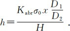
In the formula: h is the wear thickness of the roll in the radial direction; Kabr is the adhesive wear coefficient; σ0 is the surface contact stress of the roll; x is the relative sliding distance of the contact point; D1 is the diameter of the target roll for wear analysis; D2 is the diameter of the paired roll ; H is the hardness ratio of the paired rolls.
It can be seen from the above formula that the wear depth of the roll is proportional to the adhesive wear coefficient, the contact stress between the rolls, the sliding distance and the diameter ratio, and inversely proportional to the hardness ratio between the two rolls; when the material of the roll is determined, the adhesive wear coefficient and the two rolls The hardness ratio between is determined. According to the analysis of the relationship between the contact stress between the rolls and the roll diameter ratio in the existing literature, it can be seen that the contact stress between the rolls increases with the increase in the diameter ratio; according to the above formula and the aforementioned rolling process, the six-high UCM cold rolling mill work roll and intermediate roll The analysis results of the contact stress between the intermediate roll and the support roll, and as shown in Figure 5, the contact stress between the work roll and the strip is along the work roll when the strip shape control process is not applied under the same rolling parameters. The distribution of the direction of the body axis shows that the surface wear of the work roll body is caused by the contact between the work roll and the strip steel and the work roll and the intermediate roll when the roll rotates one week, and the wear of the intermediate roll body is caused by the intermediate roll and the work roll and the intermediate roll and the support The contact between the rollers is caused, and the wear on the surface of the support roller body is caused by the contact between the support roller and the intermediate roller. Therefore, the maximum wear depth of the work roll body caused by the three rotations is the largest, the middle roll is the next, and the backup roll is the smallest.
From the distribution of the contact stress between the rolls when different plate shape control processes are applied, it can be seen that when the work roll is shifted, the contact stress distribution between the work roll and the intermediate roll will be deflected, and the peak of the indirect stress between the intermediate roll and the work roll in the reverse direction of the roll shifts. The amount of rolls increases sharply. In the cyclic rolling process, the distribution of the wear depth component of the middle roll body caused by the contact between the middle roll and the work roll will produce asymmetry in the axial direction of the middle roll body, which will further cause the contact stress distribution. Increased unevenness and increased wear; when the intermediate roll shifting process is used, the contact stress between the intermediate roll and the work roll and the backup roll is deflected, resulting in a sharp peak of the contact stress on the side of the anti-shifting roll along the axis of the intermediate roll. Increase; in the cyclic rolling process, the wear depth in the axial direction of the intermediate rolls, work rolls, intermediate rolls and backup rolls will all increase sharply in the reverse direction of the intermediate rolls, resulting in contact between the rolls. The unevenness of stress distribution and wear is further increased; and the application of the intermediate roll bending process increases the uniformity of the contact stress distribution between the intermediate roll and the work roll and the support roll, which helps to improve the roll body caused by the contact between the rolls. The uneven distribution of directional wear.
4. Conclusion
Different rolling production lines optimize the roll shape and adopt different shape control techniques to ensure the quality of the rolled shape. In six-high UCM cold rolling mills, work roll shifting, intermediate roll shifting and bending rolls are usually used to control the shape quality of cold-rolled sheets. However, the use of different shape control techniques will affect the contact stress distribution between the rolls and The size has different effects. Based on the six-high UCM cold rolling mill of a cold rolling mill and the shape control process parameters used in rolling, this paper analyzes the influence of the shape control process on the contact stress distribution between the rolls and the roll wear. conclusion as below:
1) In a six-high UCM cold rolling mill, both the work roll shift and the intermediate roll shift will cause the distribution of the contact stress on the surface of the roll itself and the roll directly in contact with it to deflect along the axis of the roll, and the unevenness will increase; The implementation of the roll process will increase the uniformity of the surface contact stress distribution along the axis with the remaining two contact rolls.
2) In the normal rolling process, in the six-high UCM cold rolling mill, the maximum value of the wear distribution in the axial direction of the work roll is the largest, followed by the middle roll, and the back-up roll is the smallest.
3) In a six-high UCM cold rolling mill, the work roll and intermediate roll shifting will cause unevenness in the surface wear of the shifting rolls, and the unevenness will increase with the increase of the shifting volume; the middle roll bending not only helps to improve The quality of the rolled shape can increase the uniformity of the surface wear of the roll at the same time.
No comments:
Post a Comment