Abstract: This article presents an in-depth review of the literature on the defects of special-shaped billets, mainly focusing on the formation mechanism of defects, proposes solutions to reduce defects, shows the techniques used to investigate defects, and measures to improve the quality of molten steel and mold design in the continuous casting process , Secondary cooling modification and instrument calibration, sector support, continuous casting arc calibration, etc.
Special-shaped billet continuous casting was born in 1968. Since then, about 60 sets of special-shaped billet continuous casting machines have been installed. This article presents a literature review of special-shaped billet defects, mainly focusing on the formation mechanism of defects, and proposes to reduce defects solution. Surface defects include longitudinal cracks and transverse cracks. Internal defects are the cracks generated during the bubble and solidification process. The outlook includes the techniques used to investigate the defects: metallographic investigation, computational fluid dynamics, thermodynamics and thermomechanical models. The measures taken in the continuous casting process include improving the design of the immersion nozzle (SEN), modifying and calibrating the instrumentation of the secondary cooling, and supporting the arc section.
Special-shaped billets can be cast open, quasi-protected casting and protected casting. These three types of casting methods are shown in Figure 1. Each method has its advantages and disadvantages, as shown in Table 1. Open casting is generally used for small cross-section special-shaped billets. Although there is also a single nozzle casting method, each mold is usually cast with two sizing nozzles. For open casting sizing nozzles can be automatically and quickly replaced. Open casting is simple and has high production efficiency. However, the problem encountered by open casting is the secondary oxidation of silicon and manganese in the molten steel. There are also aluminum oxides formed by feeding aluminum wires in the mold to strengthen deoxidation. The quality problems encountered by open casting are shown in Table 1.


 |
Figure 1: a is open casting; b is quasi-protected casting; c is immersed double nozzle protection casting; d is single immersed nozzle casting
 |
Table 1: Advantages and disadvantages of 3 casting modes |
Most special-shaped billet continuous casting uses quasi-protective casting. This method combines the advantages of open casting and protective casting. Two nozzles are used to introduce molten steel into the mold, so that mold powder can be used. Although there are also horizontal nozzles used in experiments, vertical nozzles are usually used to enter the crystallizer. When casting large cross-section profiled billets and aluminum killed steel, the use of stopper rod mechanism or sliding plate mechanism combined immersion nozzle casting method. Considering the limitation of crystallizer space, a single inlet nozzle was also tested.
The special-shaped billet mold can adopt a copper tube structure, which is the same as the usual billet, or a four-plate structure like the slab mold, as shown in Figure 2. Copper tubes are usually used for the production of special-shaped billets with small and medium-sized sections. The four-plate structure mold is composed of two narrow faces and two wide faces. It can also be designed to insert special-shaped billets in the combined special-shaped billet mold. In this way, two methods can be used to organize the production of billet copper tubes. This solution has been used in the mold with medium section.

Figure 2: Special-shaped billet mold: a tube-type copper tube; b is a four-plate combined mold
The wide-faced copper plate of a typical plate-type special-shaped billet mold uses a row of round holes for cooling, and the narrow-faced copper plate is cooled by a water tank, as shown in Figure 3.

Figure 3: Typical narrow-face and wide-face cooling water circuit design for special-shaped billet mold
The plate-type special-shaped billet mold has the following characteristics: (a) There are several cooling water cavity methods to take away heat: the sink behind the copper plate, the copper plate has a cooling water hole ring, and the complete cooling water hole. The cooling grooves or holes are separated by a certain distance, and they are biased toward the hot surface at the position of the copper plate; (b) The combined mold has high rigidity; (c) The lateral geometric dimensions of the cooling water channel are stable; (d) Different taper modes are easily achieved; (e) )higher cost.
Compared with the billet continuous casting machine, due to the complexity of the structure of the shaped billet mold, especially the irregular transverse section, the fluid flow and thermodynamic models are widely used for heat transfer calculations.
1.Surface defects
The surface defects of the special-shaped billet are basically similar to those of the billet, but there are some special places. These defects include pinholes, slagging and longitudinal cracks.
1.1Pinhole
This defect mainly occurs in the casting method that uses sizing nozzle oil lubrication. The appearance of pinholes causes quality problems in the final rolled H-beam, especially at the nests of the web and flanges. The heating process of the rolling steel cannot eliminate this. Defects, the first few passes of special-shaped billet rolling have free spreading in some parts (there is no restriction to limit the spreading). The pinhole defect has no oxide scale in the continuous casting slab stage, and it is full of oxidation after the steel rolling heating furnace. Iron sheet. The pinholes are formed due to the moisture in the lubricating oil (or the inhalation of moisture in the oil supply pipeline), excessive oil supply, uneven lubricating oil distribution, too thick oil groove gap (greater than 0.5mm), due to splashing Caused by the blockage of the oil circuit, sudden changes in the molten steel level, the use of punching measures, poor molten steel deoxidation, etc., the use of mold electromagnetic stirring can help eliminate pinholes.
1.2Scar
A small breakout occurred on the cast billet, but it immediately cooled and healed, and no accident and metal loss occurred. An example of this defect that occurs in the shaped blank is shown in Figure 4. This is caused by the annular strain in the hot zone of the shaped blank in the mold, or caused by bonding. The mechanism of opening in oil lubrication is shown in Figure 5.

Figure 4: Scars on the inner arc surface of the flange with a width of 670mm of the shaped blank

Figure 5: Healing mechanism of local breakout in the mold (left 1 is the temperature of the mold liquid level; left 2 the liquid level in the mold rises and the lubricating oil on the hot surface dries up, resulting in a lack of lubrication area; left 3 the mold liquid level drops through the oil-deficient area , The blank shell is bonded to the copper plate, the stretch-straightening machine is still working, and the casting billet descends; the left 4 stretch-straightening machine makes this place thin and tear; the left 5 molten steel overflows, and then cools and solidifies on the copper tube wall to heal)
1.3Wrap slag
Foaming scum is formed when molten steel in open casting comes into contact with the atmosphere and oxidized slag. This scum usually contains manganese silicate. If the silicon content is too high (due to the low Mn/Si ratio), the precipitation of silicon oxide will occur, resulting in high viscosity. , The risk of scum entering the surface of the special-shaped billet increases, and a breakout accident will occur in particularly serious cases. In addition, feeding aluminum wire into the mold also causes high viscosity of the scum. High-viscosity scum cannot be avoided, and it is difficult to reach the ideal and correct position. The two situations are summarized in the ternary phase of SiO2-MnO-Al2O3 in Figure 6. In the picture.

Figure 6:Red circle part: the dangerous area of solid phase precipitation (silicon oxide precipitation due to low Mn/Si ratio, or aluminum oxide inclusion precipitation due to improper aluminum wire feeding in the mold), located in the open casting meniscus Scum on the surface
A similar situation occurs when protective casting (using a funnel or immersion nozzle) is used. The mold powder absorbs alumina and causes the viscosity to increase, or the elements in the molten steel and the oxides of the mold powder cause the viscosity to increase (such as , The dissolving titanium in the steel reacts with the silicon oxide in the slag). The turbulence formed by molten steel injection, excessive stirring power, and the immersion nozzle or the shallow insertion depth of the funnel will cause the mold slag to be engulfed in the steel.
1.4Reticulated cracks
These cracks are related to the copper content in the steel. The copper content of smelting slabs with a high proportion of scrap steel is generally high. The air gap between the slab shell and the copper plate or copper tube increases, and the grain size becomes larger. If the copper content is high, Cracks will occur in this place. Figure 7 shows the reticulated cracks on the surface of the H-beam after being rolled by Dragon Steel. In this steel plant, the copper content is controlled to be less than 0.15%. In order to meet this requirement, a higher proportion of molten iron is used in electric furnace smelting. The copper content in the steel is related to the type and quality of the scrap steel added, as shown in Figure 7 for the loading ratio.

Figure 7: Reticulated cracks on the surface of H-beam after hot rolling at Dragon Steel Plant
1.5Longitudinal cracks
This defect is quite common in special-shaped billets. The defect is formed in the mold and is similar to the longitudinal cracks of slabs and large-section rectangular billets (see Figure 8). Observing the high-magnification photo of the rolled product, it is found that there is oxidation inside. Phenomenon (the sample is polished and does not need to be corroded), decarburization (using 2% picric acid to corrode the sample), see oxygen penetration (using alkaline sodium chromate hot corrosion). The factors that cause longitudinal crack defects include the chemical composition of molten steel, the nature of the mold powder, the vibration deflection of the continuous casting machine mold, the change in mold cooling water flow and temperature, and the incorrect secondary cooling flow.

Figure 8: 1050mm width of special-shaped blank, longitudinal cracks at the junction of flange and web
The chemical composition of steel: From the early research, the sulfur content has more influence on the longitudinal cracking (see Figure 9). Another related element is the carbon content. It is necessary to avoid the occurrence of peritectic phase transformation, which is used in slab continuous casting. There is a lot of experience in longitudinal cracking defects. For example, experts from Pohang in South Korea showed the cracks of special-shaped billets that were cleaned by more than 2000 furnaces. They found that the carbon content is within the range of 0.12~0.13%, which corresponds to the peritectic ladle. Because of the heavy crystal reaction. Stahwerke Thuringen previously recommended a maximum carbon content of 0.08% to avoid the peritectic zone. In order to achieve the required mechanical strength, the lower limit of manganese content was set at 0.60%. Recently, the calculation of the carbon content range of the peritectic reaction has begun to use the thermodynamic commercial software FactSage and ThermoCalc.
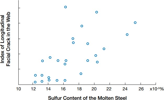
Figure 9: The influence of the sulfur content in the steel of the profiled billet web on the longitudinal crack index
Mold powder: The mold powder can be used with funnels and immersion nozzles. The longitudinal cracks that appear are known. For example, in the Stahlwerke Thüringen steel plant, the use of high-alkalinity and low-viscosity mold powder is effective for low-speed casting (<1m/min). The effect of profiled blanks is very good, as shown in Figure 10. The use of weak cooling on the meniscus can obtain flowing mold powder. Even lower liquid mold powder penetration and lubrication capabilities can partially offset the risk of longitudinal cracks caused by low viscosity. In other conditions, JFE Steel Mitzushima Steel Plant It was found that the opposite phenomenon was found. The low-viscosity mold powder did not solve the problem of longitudinal cracking (of course, longitudinal cracking has other causes combined). In the cold area of the meniscus (for example, near the nozzle area), the mold powder has reached the limit of its performance and cannot help the longitudinal cracks, as shown in Figure 11.

Figure 10: Using different mold fluxes at StahlwerkeThuringen steel plant, low drawing speed of small-section shaped billets (less than 1m/min), testing the influence on the formation of longitudinal cracks
 |
Figure 11: Longitudinal surface cracks and mold flux in the 1050mm width profiled blank |
Continuous casting speed: The aforementioned study by Pohang in South Korea shows a linear relationship. When the continuous casting speed increases, the solid shell becomes thinner, the heat flux increases, and the strain increases, resulting in more cracks.
Secondary cooling process: Increasing the strength of secondary cooling increases the tendency of longitudinal crack formation. This relationship was shown at Kawasaki Steel Plant (now JFE Steel Plant). The effect of sulfur content has also been discussed, see Figure 12.

Figure 12: Under different secondary cooling flow regimes, the effect of sulfur content on the formation of longitudinal cracks
Mathematical models are widely used to find and solve defects. For example, Jin Yi Steel uses models to optimize the secondary cooling to avoid these cracks. They use ANSYS software for heat engine model calculations and MATLAB software to optimize parameters. China's Maanshan Iron and Steel Company takes into account all heat transfer mechanisms and completely uses an optimized secondary cooling model to avoid longitudinal cracks (see Figure 13). These experiences are summarized in Table 2. Their functions can be divided into: (a) Metallurgical factors: lower sulfur content; composition to avoid peritectic phase change; (b) Mold powder: use high basicity mold powder and uniform heat transfer Effect; (c) Mold design: avoid longitudinal cracks at the junction of the web and flange; (d) Secondary cooling process: use weak cooling in the first stage of the secondary cooling; good lateral nozzle distribution.
![]()
Figure 13: Schematic diagram of the heat transfer mechanism of the second cooling of Maanshan Iron & Steel Co., Ltd., using digital simulation to optimize the second cooling to avoid longitudinal cracks
Table 2: Summary of longitudinal surface crack defects of special-shaped blanks |
2Internal defects
The internal defects of the shaped billet are similar to the billet, bubbles, core network cracks and internal cracks at the flange edges are all discussed below.
2.1Bubbles
This defect is close to the surface of the cast slab and perpendicular to the surface. If the defect inside the cast slab is serious, it can be seen with naked eyes on the rear face of the flame cutting machine. This defect often occurs on the cast slab in the first batch of the tundish, or some Some problematic heats, or all heats, when the gas segregation between the dendrites is enough, they leave the surface of the shaped billet during the cooling process, and they stop below the meniscus. The static pressure of molten steel is greater than the bubble pressure and cannot float and stay in the steel (see Figure 14).
![]()
Figure 14: Special-shaped billet bubbles: a is a horizontal low magnification, b is a radiographic inspection photo
Bubbles are caused by too much gas dissolved in steel (oxygen, nitrogen, hydrogen). This phenomenon has been simulated in the early continuous casting machine. From the point of view of secondary oxidation, Mn-Si killed deoxidation is used to solve the problem. Blockage of the nozzle (provided that the secondary oxidation is not very strong) and bubble defects are a compromise solution, see Figure 15.

Figure 15: Optimizing the deoxidation system in Mn-Si killed steel to reduce bubbles and prevent nozzle blockage
Dragon Steel Factory reported a case of air bubbles in the casting of special-shaped billets using a sizing nozzle. 80kg aluminum and 40kg CaFe were used to deoxidize the steel at the time of tapping to make the oxygen content less than 10pp. If the temperature of the molten steel is too low, the tundish nozzle needs to burn oxygen. Local oxygen levels rise. From the grinding and cleaning inspection of the special-shaped billet produced, see Fig. 16, the changes in the refining furnace and continuous casting process were studied in an all-round way. The conclusion is that the refractory material used in the tundish repair is too humid, so bubbles are generated on the special-shaped billet. defect.
![]()
Figure 16: Cleaning the air bubbles in the special-shaped billet at the Dragon Steel Plant
2.2Reticulated core cracks
This defect is equivalent to the defect caused by the centerline segregation of the slab. Insufficient length of the secondary cooling support or insufficient cooling during the secondary cooling process causes the billet to bulge. In severe cases, the internal bulge of the web cracks, as shown in Figure 17a. The high level of center segregation and crack formation can be manifested during the rolling process. The measures to avoid this bulging defect are to check the blessing effect of the roll and the centering inspection of the sector equipment.
Japan’s Mitzushima Steel Plant and Kawasaki Steel Plant reported a center crack case. The basic radius of the caster is 12.5m. The 400x460x120mm special-shaped billet and 287x560x120mm special-shaped billet are cast with funnel nozzle mold powder. Figure 17b shows the sulfur content and the pulling speed. This problem is solved by strengthening the cooling of the web and strict inspection of the roll gap.

Figure 17 a is the crack in the center of the web, and b is the effect of sulfur content and pulling speed on the formation of the crack in the center of the web.
2.3Internal cracks at the edge of the flange
This particular defect was studied because it caused a steel breakout accident. Improvements were made in the Kurashiki Steel Plant of JFE Company to solve this problem. Table 3 shows the research and solution. In normal casting, certain cracks are found in the attachment of the flange end, which is consistent with the cracks near the corners of the billet and slab, as shown in Fig. 18. This defect is solved by optimizing the taper of the flange end of the mold.
 |
Table 3: JFE Company Kurashiki Steel Plant's research on flange ends |
 |
Figure 18: Cracks at the flange end of the normal casting profile billet at the Kurashiki Steel Plant of JFE Company (no breakout) |
3Conclusion
Special-shaped billets have been produced for more than 50 years, but they still have surface quality and internal quality defects. Some defects are similar to billet defects, and some are the same as slab defects. Special-shaped billets have unique solidification defects due to their special shape. The defective steel mills must be studied to solve them. It is very important to understand the characteristics of defects. Simulation helps to understand the formation mechanism of defects and propose correct solutions.
No comments:
Post a Comment